
Metalworking and optomechanical manufacturing
We manufacture mechanical and optomechanical parts from drawings, 3D models or assembly requirements. The workshop produces holders, lens mounts, adapters, housing components and tooling for optical instruments and experimental setups.
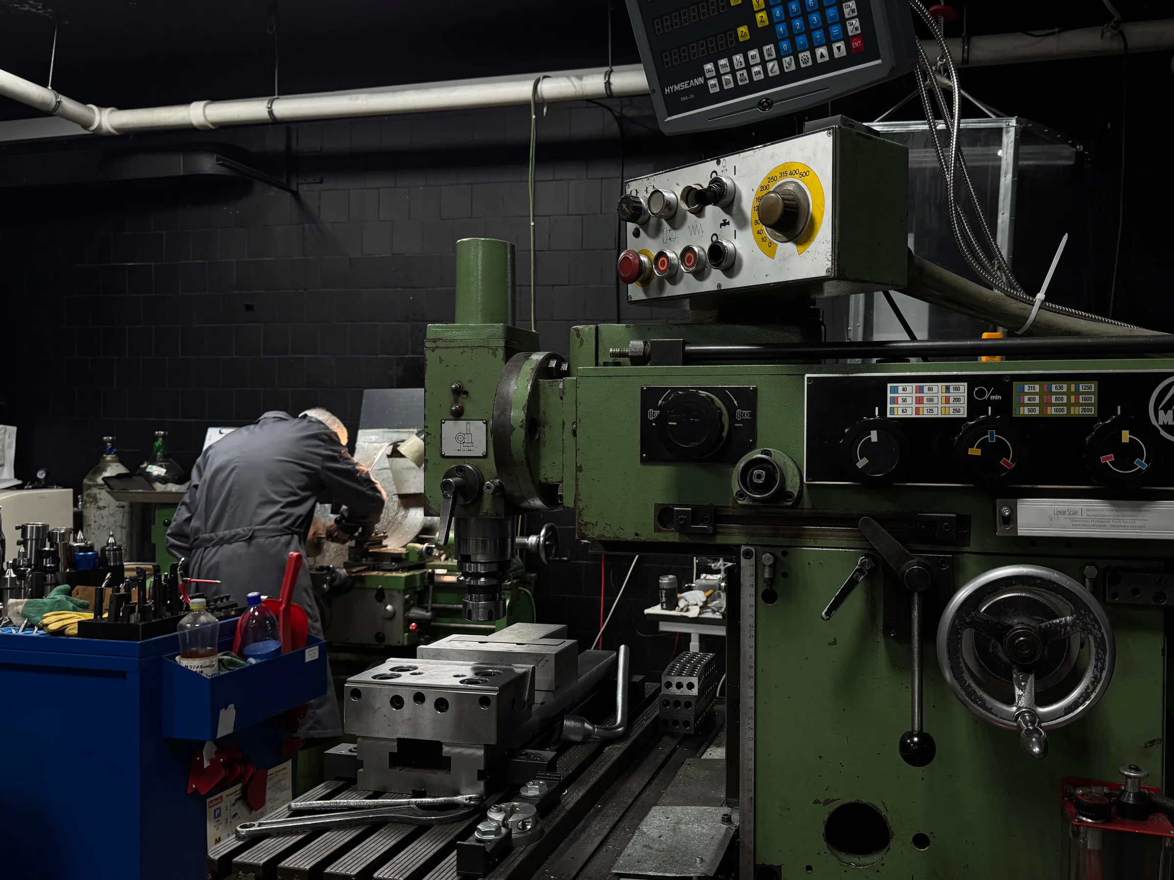
Our facilities include manual and CNC lathes and milling machines, dimensional inspection and 3D printing. The workshop can make a single part, a batch or a series. For a new product, a part can first be checked in the assembly, then revised and manufactured again.
What the workshop can do
Work can start with complete documentation, an overall assembly or requirements for an individual part.
- Manufacture a holder, lens mount, adapter, housing component or mounting part for an optical system.
- Make a single part for a model, prototype or repair replacement.
- Manufacture a batch of parts for assembly or series production.
- Revise a part after a fit check or laboratory test.
- Manufacture tooling and fixtures for assembly, machining or measurement.
- Check part geometry by printing a 3D prototype before machining the metal.
Send a drawing, 3D model, sketch or overall assembly. Specify the material, mating dimensions, threads, tolerances and surfaces that affect operation.
Turning and milling
Equipment is selected according to part geometry, material, tolerance and the number of operations.
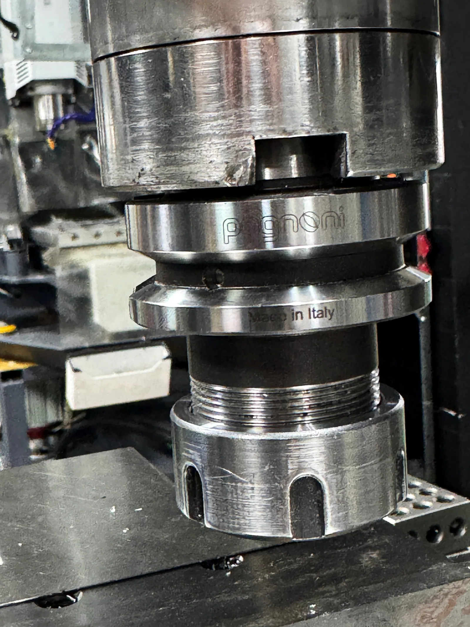
Equipment, workholding and cutting tools are selected for the geometry and manufacturing process.
The workshop has manual and CNC lathes and milling machines.
Where the design requires metal elements to be joined, welding can be included in the project. Our team will clarify the welding method and joint requirements based on the material and purpose of the part.
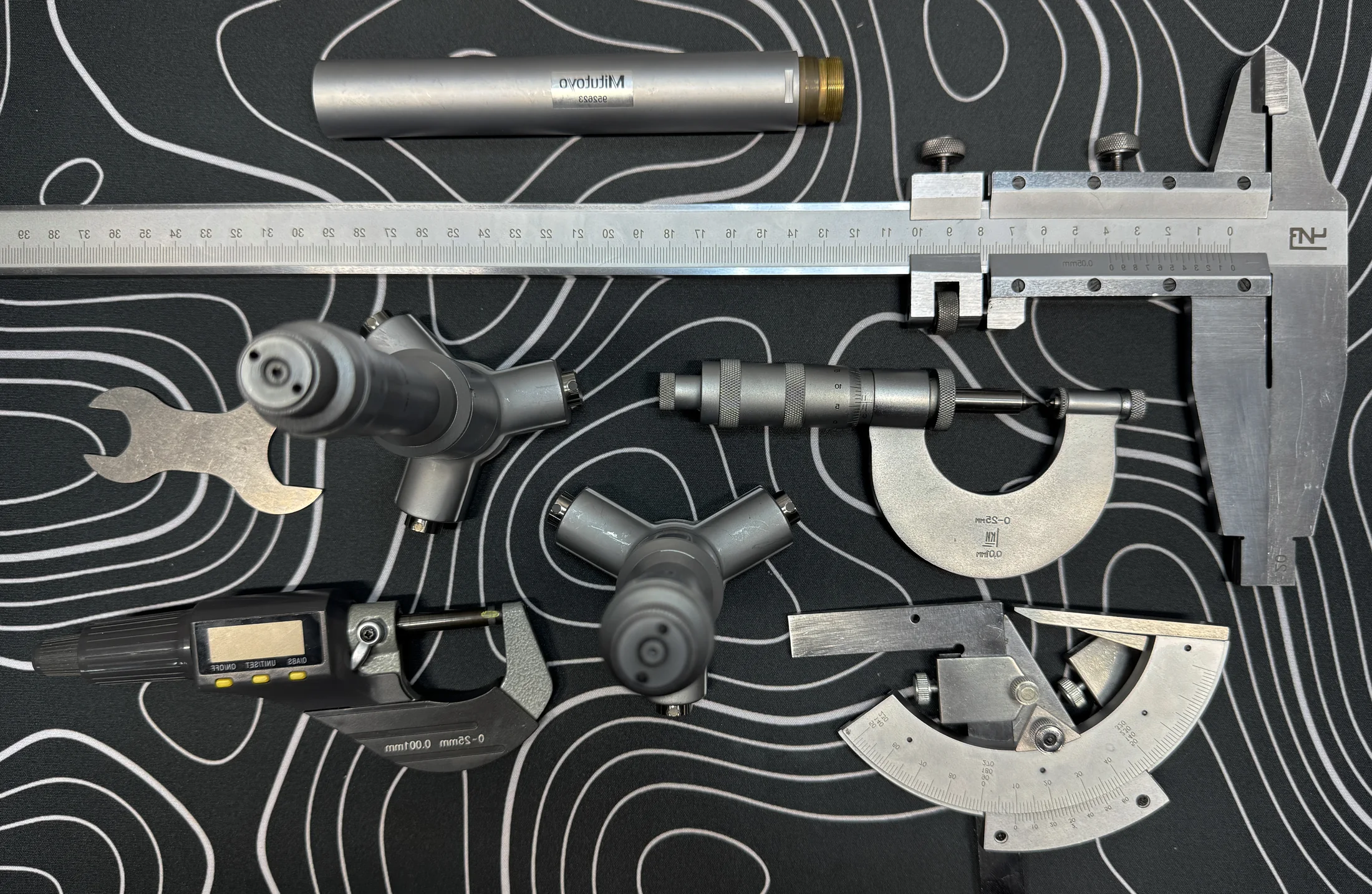
Tools for checking linear dimensions, diameters and part geometry.
Dimensional inspection
Available instruments include callipers, micrometers, measuring gauges, verified bore gauges covering 2 to 100 mm and other tools. Inspection dimensions and methods are best agreed before machining starts.
For linear positioning during machining, digital readouts with a 5 µm resolution are used. This figure does not determine the tolerance of the finished part.
Tolerance, surface roughness and reporting requirements depend on the part. Our team will confirm achievable parameters and inspection methods after reviewing the input data.
Parts for optical systems
The workshop manufactures lens mounts, holders, adapters, housings, mounting plates and fasteners for optical instruments and test setups. An engineer can check the part in the overall assembly and refine the model to account for neighbouring components.
We cut metric and inch threads used in optomechanics. The thread profile and size are agreed from a drawing or mating part.
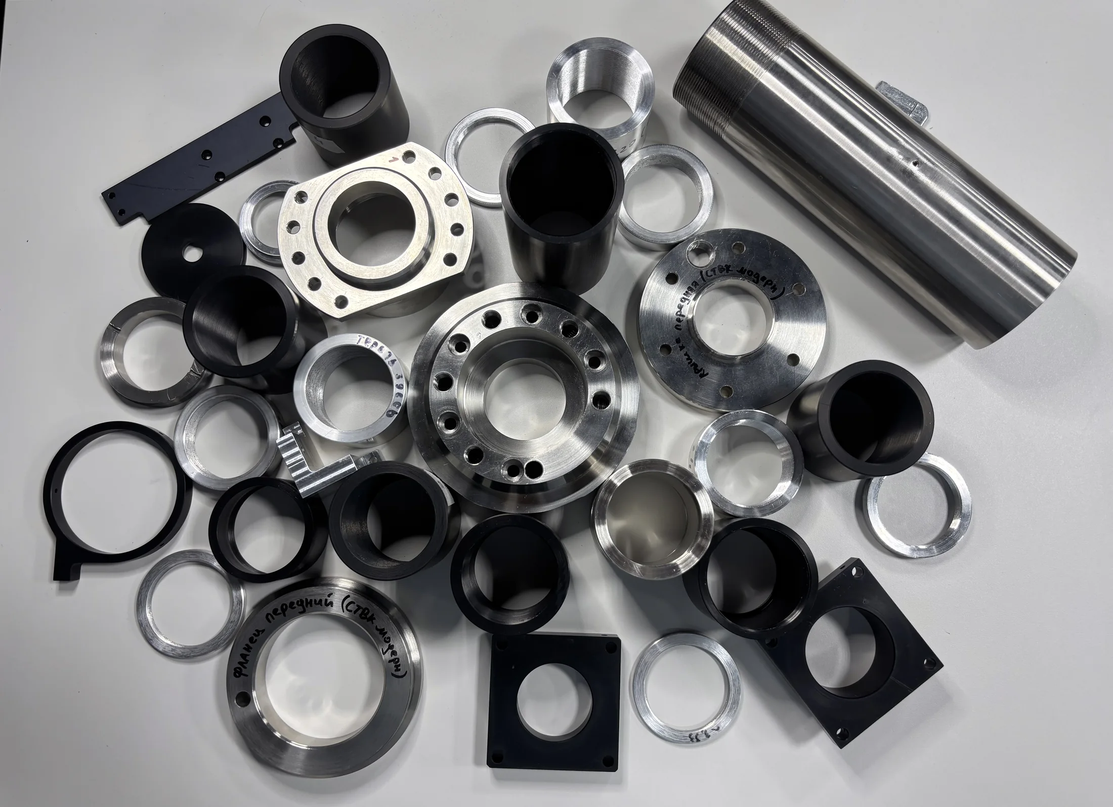
Mating surfaces, fasteners and threads are coordinated with the overall product assembly.
From a single part to series production
The workshop accepts single-part, batch and series orders.
The engineer passes the completed model directly to the workshop specialist. Questions about datums, dimensions and the manufacturing process can be resolved before the machine starts.
After a fit check or laboratory test, the team can revise the model and manufacture the next version. Once the design and process are verified, the workshop produces a batch to the agreed documentation and passes the parts to series assembly.
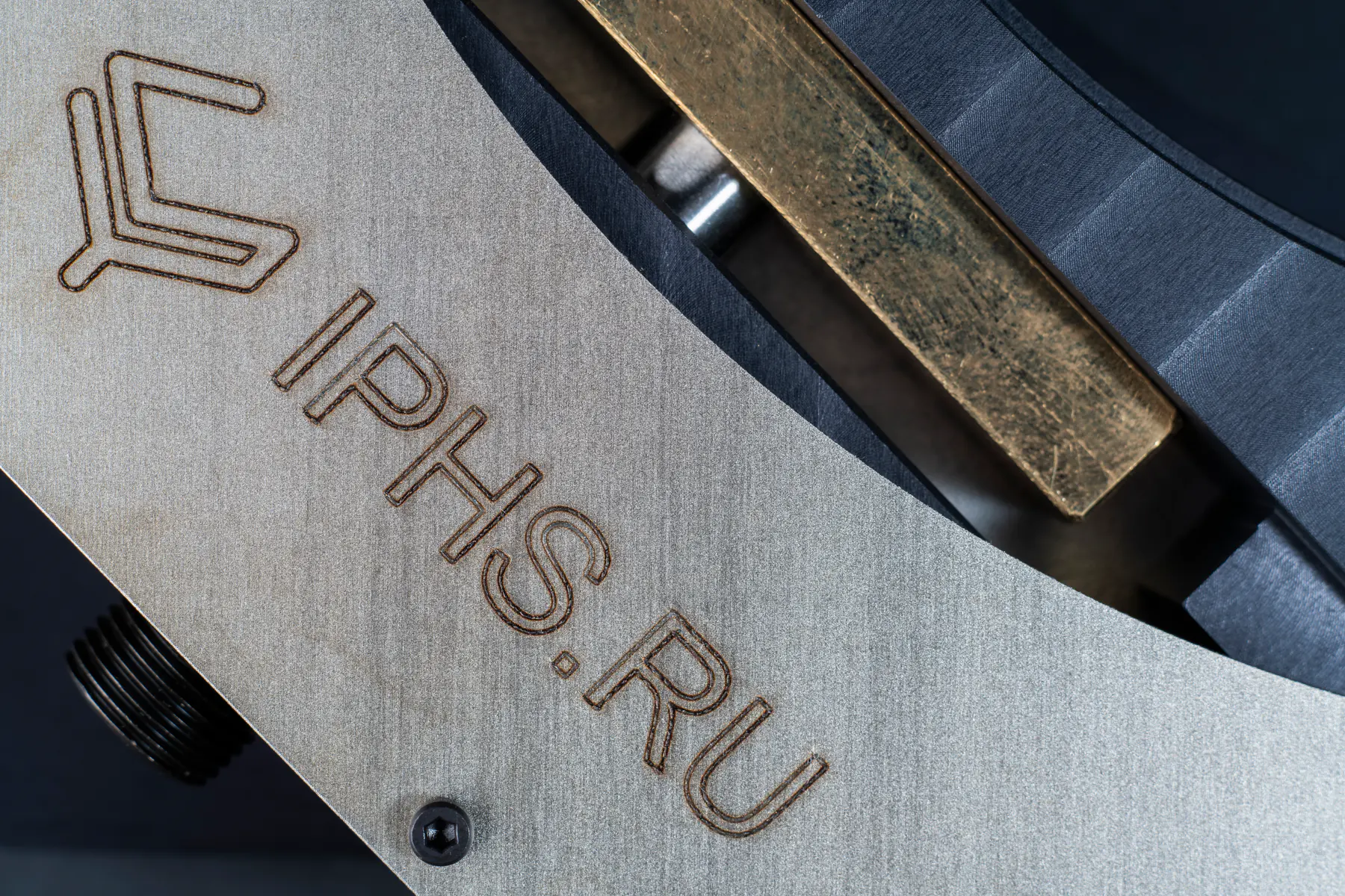
The design can be checked in an assembly, revised and then used for repeatable production.
Tooling and fixtures
For a non-standard operation, our team designs and manufactures its own tooling and fixtures. This allows workholding, tool access and part inspection to be considered within one process.
3D prototype before machining
Before machining metal, the geometry can be checked by printing a 3D prototype. Where needed, the printed part helps assess dimensions, component positions and assembly access.
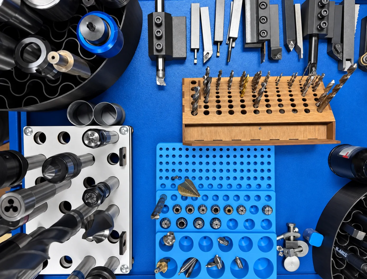
Tools and fixtures are selected according to part geometry and the operation sequence.
How the work proceeds
We agree the manufacturing process, inspection dimensions and acceptance method before manufacturing starts.
- 01
Review the inputs
We check the drawing or 3D model, material, mating features, threads, tolerances and surface requirements.
- 02
Select the manufacturing process
We define the operation sequence, equipment, workholding, tooling and inspection dimensions.
- 03
Prepare for manufacturing
We develop the CNC programme and tooling and, where needed, first print a prototype to check geometry.
- 04
Manufacture and inspect
We machine the part and check the agreed dimensions with the available measuring instruments.
- 05
Review the result
We deliver the part for acceptance, assembly or laboratory testing and record findings for the next iteration.
What you can receive
The result is a part made to the agreed drawing or 3D model. The scope may also include tooling, a 3D prototype and dimensional inspection information in the agreed format.
Related stages
Metalworking can form part of prototyping an optical system or laboratory assembly. After the design is verified, the workshop can produce parts for series assembly or contract manufacturing of the product.
Before we start
Answers to common questions before an initial project assessment.
01Can I order a single part or a production run?
Yes. The workshop accepts single-part, batch and series orders. For an assessment, send a drawing, 3D model or part description, with the quantity and critical dimensions.
02What should I send for a quotation?
Send a drawing, 3D model, sketch, technical brief or overall assembly. Include the material, quantity, threads, tolerances, surface requirements and acceptance method where possible.
03What accuracy can you achieve?
Accuracy depends on geometry, material, dimensions, workholding and the inspection method. The digital readout has a 5 µm resolution, but this does not define the finished part tolerance. Our team will confirm achievable parameters after reviewing the model.
04Which metals can the workshop machine?
Machinability is assessed for the specific material grade and part. Specify the alloy in your enquiry so our team can review it alongside the geometry, dimensions and surface requirements.
05Can you make threads for optomechanical components?
Yes. The workshop works with metric and inch threads used in optomechanics. For an assessment, provide the thread profile, size and mating part or its drawing.
06Can I order tooling or a 3D-printed prototype?
Yes. Our team designs and manufactures tooling and fixtures. Part geometry can be checked beforehand by printing a 3D prototype.
Discuss part manufacturing
Send a drawing, 3D model or task description. Specify the material, quantity, critical dimensions and purpose of the part. Our team will review the materials and propose a manufacturing process, inspection scope and next step.