
Engineering project archive
Rigid borescope for a nuclear power plant
Task: observation through a high-temperature zone under elevated radiation
 PHOTO 01
Rigid borescope for observation at elevated temperatures and radiation levels.
Initial task
Visual inspection at high temperatures and radiation levels
A system was required for visual inspection of objects at elevated temperatures and radiation levels. The borescope had to operate at distances from 0.5 to 8 m, provide a field of view of at least 30° and keep the optical path inside a narrow metal housing.
The contractual technical brief specified temperatures of 600–700 °C in the observed room. Separate temperature limits were set for the internal optics and camera, to be refined through testing of the thermal model.
Optical design and prototype
Designing the optics and testing a physical model
Work began with a conceptual layout in Zemax. We calculated a room-temperature version and a hot-zone version using radiation-resistant 200-series glass. In parallel, we selected available materials, refined lens radii to match actual sizes, and selected the camera, illumination layout and coating requirements.
The first assembly used polymer lenses and standard optomechanics. This model helped verify ray paths, layout and alignment procedures before glass optics and the long metal housing were manufactured.
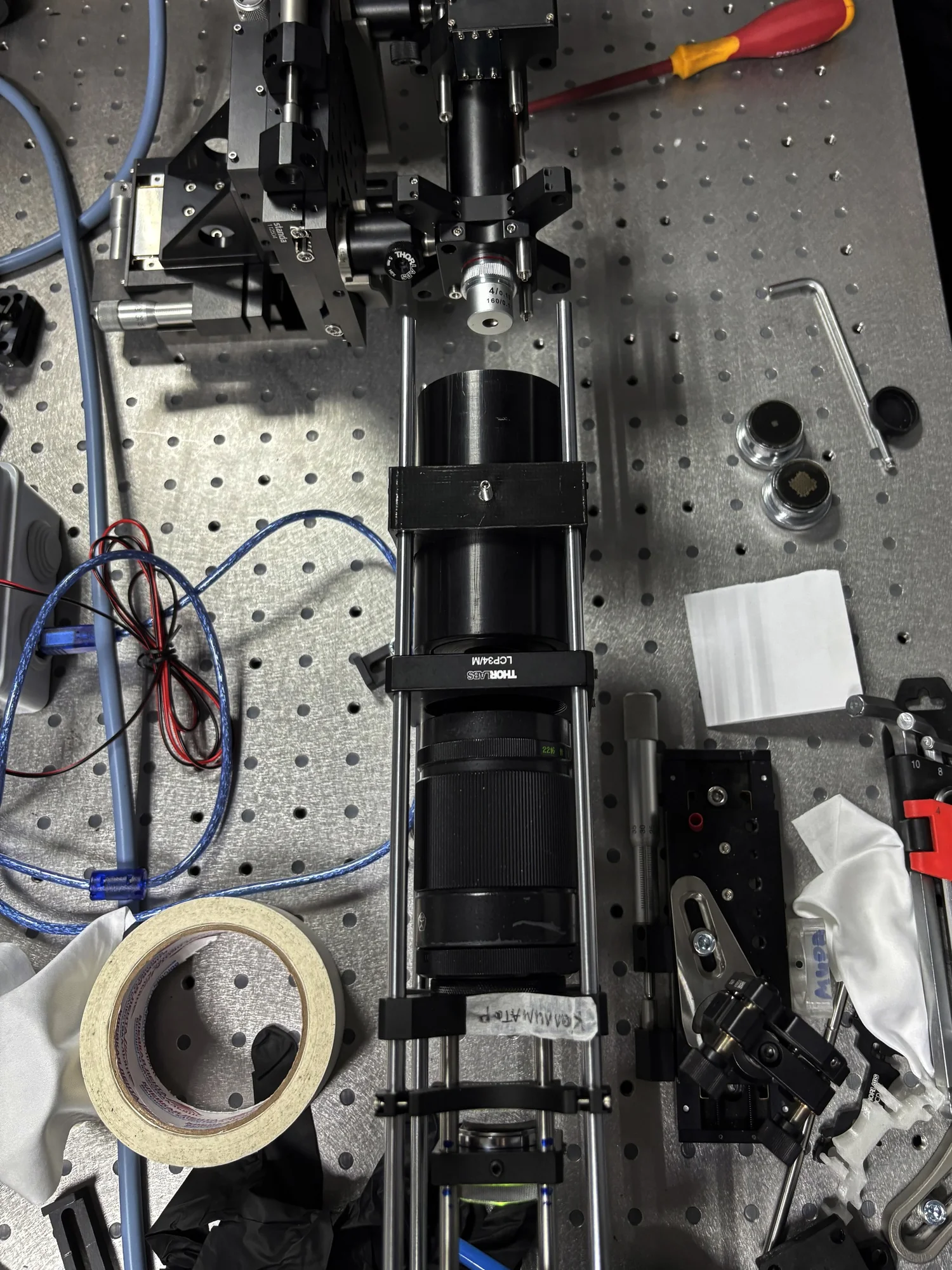 PHOTO 02
 SIMULATION 01
Thermal revisions
Thermal testing changed the design
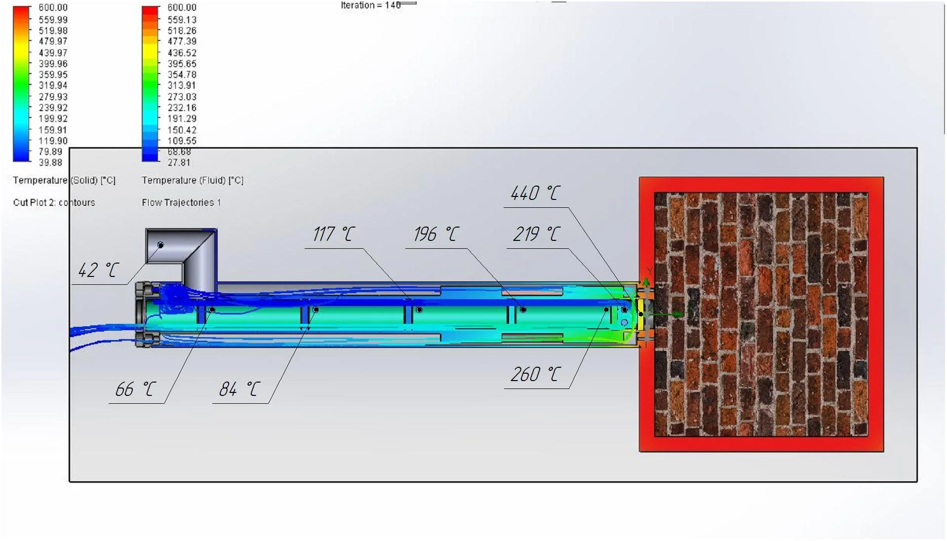
After testing the polymer-lens model, our team received the results of laboratory tests of the air-cooling system from the client. In one test, the furnace reached 614 °C, while temperatures in the measurement zones remained substantially lower.
The next test revealed a critical condition. When cooling stopped, the temperature in the first chamber rose from 44 to 175 °C within a minute and fell rapidly when cooling resumed. The front glass cracked.
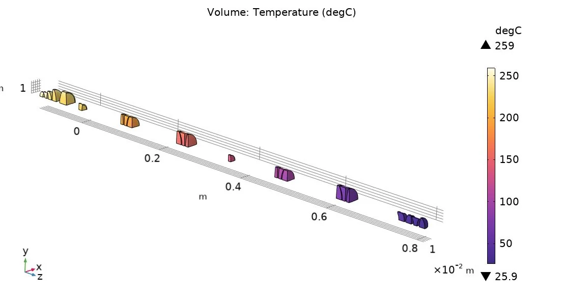
These results became engineering constraints. We considered thermal clearances at different distances from the furnace, as well as heating and cooling rates. Thermal gradients in the polymer and glass versions were modelled in COMSOL. The findings guided revisions to the optical layout and housing documentation.
 SIMULATION 02
Optics and mechanics
Glass optics in a metal housing
For the working version, we manufactured lenses, mirrors, mounts, bushings, flanges and a long stainless-steel housing. Optical components underwent incoming inspection. The design retained access for assembly and alignment, as well as connections for integration with the cooling jacket supplied by the client.
Housing and optomechanical parts were manufactured in our metalworking workshop, while assembly and alignment used the facilities of the optical laboratory.
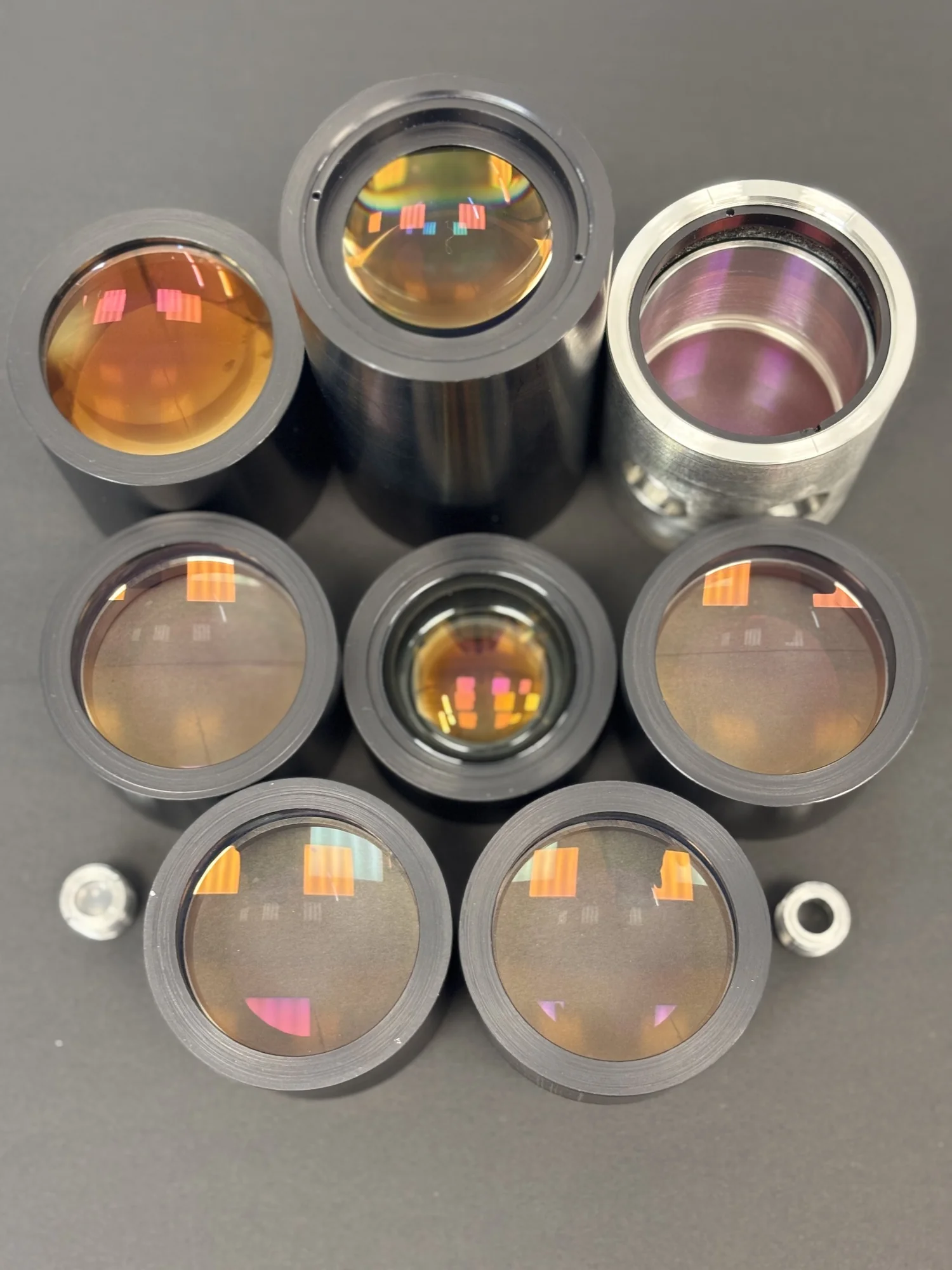 PHOTO 03
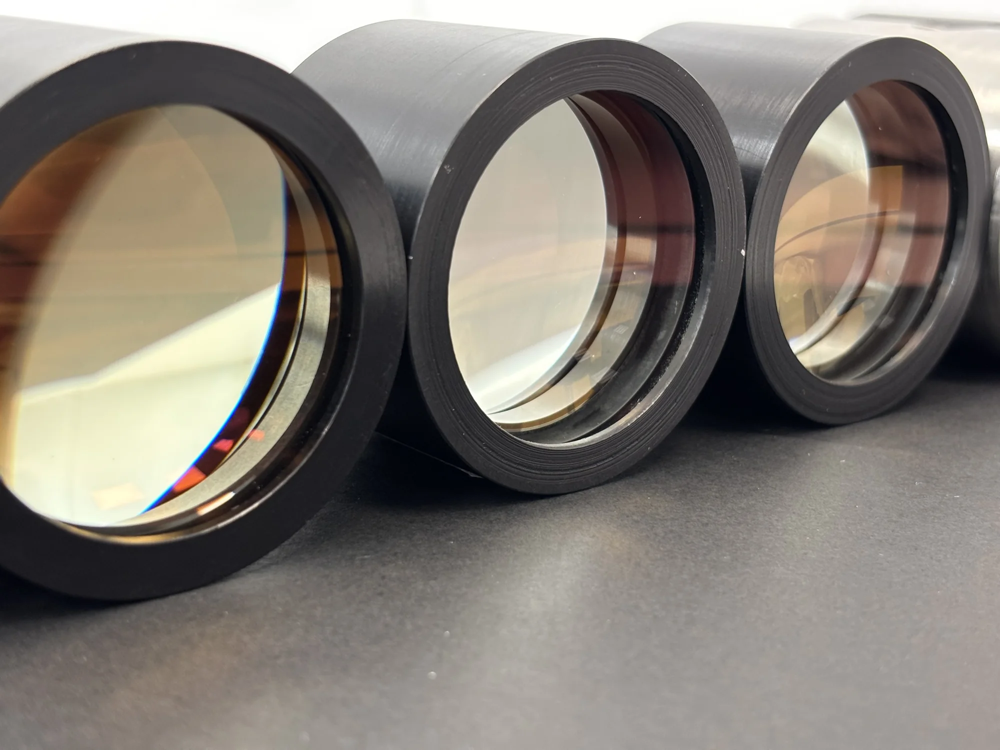 PHOTO 04
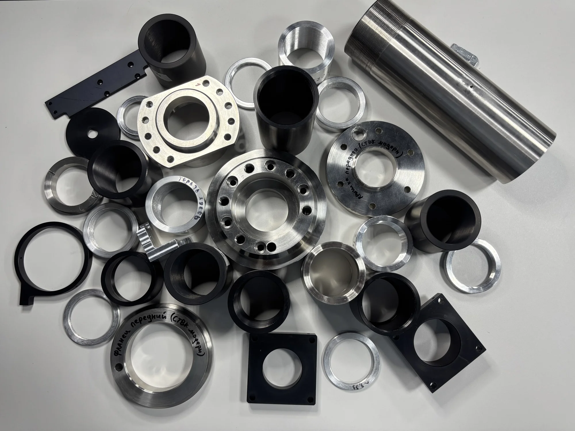 PHOTO 05
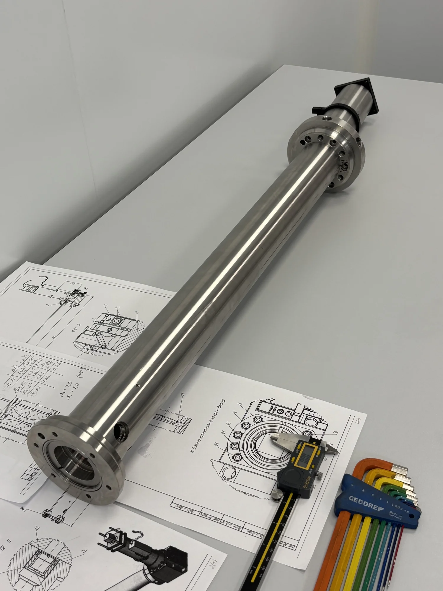 PHOTO 06
Laboratory testing
Testing confirmed the optical parameters
The assembled model was aligned using a line resolution target. The system resolved 150 lines/mm on axis and 40 lines/mm at the edge of the field, against requirements of 50 and 10 lines/mm respectively.
The measured focal length was 15 mm. A transmission of 0.5 was achieved for the long system using radiation-resistant 200-series glass, whose intrinsic transmission is lower than that of standard optical glass. To reach this value, our team improved the optical coatings. The model passed laboratory testing.
Project specifications
Key parameters
Temperature, geometry and working distance are specified requirements. Resolution values are laboratory test results.
| Parameter | Value | Status |
|---|---|---|
| Temperature in the observed room | 600–700 °C | Specified requirement |
| Object distance | 0.5–8.0 m | Specified requirement |
| Field of view | At least 30° | Specified requirement |
| Magnification | 1.0–1.5× | Specified requirement |
| Operating spectral range | 630–660 nm | Specified requirement |
| Optical system diameter | No more than 2 inches | Specified requirement |
| On-axis resolution | 150 lines/mm | Measured; requirement: 50 lines/mm |
| Edge-of-field resolution | 40 lines/mm | Measured; requirement: 10 lines/mm |
Result
From optical design to a tested model
Our team progressed from an optical design and a polymer-lens bench model to a glass system in a metal housing. The thermal shock that cracked the front glass during testing led to changes in both the optics and mechanics.
The final model verified focal length, resolution and transmission under the test programme. The project combined optical design, component manufacturing, laboratory verification and product assembly.
Project gallery
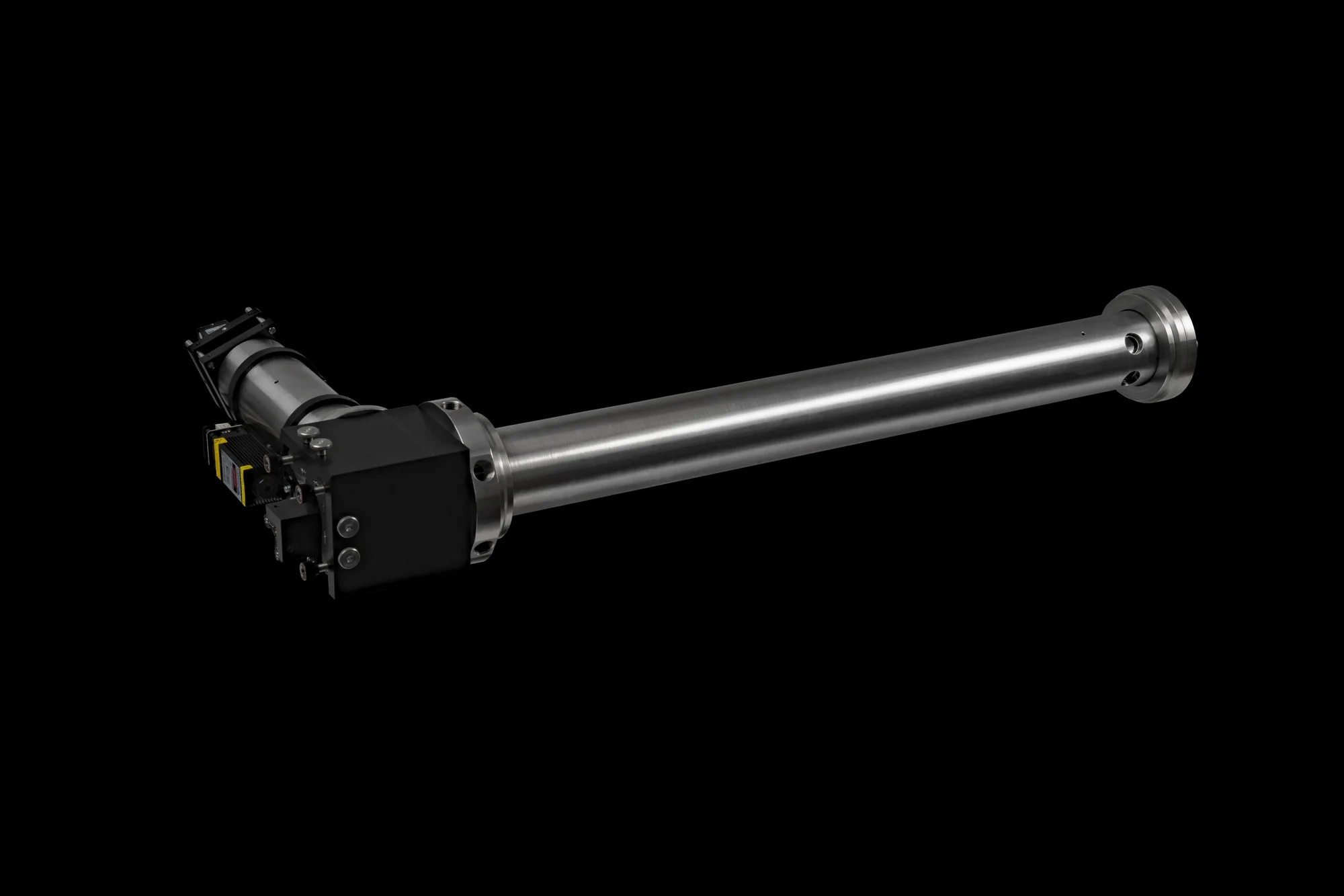
Completed borescope
Four views of the completed product: overall view, housing, flanges and alignment mechanism.
 GALLERY 01
Discuss a similar project
Send a technical brief, object and detector parameters or a description of the experimental setup. Our team will review the task and propose the scope of design, prototyping and manufacturing.