
Engineering project archive
Lens for a single-photon detector
Task: resolve two ions separated by 5 µm
 PHOTO 01
Lens for detecting resonance fluorescence from calcium ions.
Initial task
Resolving two ions in a quantum computing setup
The client needed an optical system for a quantum computing setup. It had to collect resonance fluorescence at 396.959 nm and form separate images of two calcium ions on the sensor. The ions were separated by 5 µm in the object plane.
The technical brief specified a numerical aperture of 0.45, a 400 µm field and 15× magnification. The detector had a 6 × 6 mm active area and 6.5 µm pixels. These inputs tied the optical design to the geometry of the physical setup.
Requirements
Key parameters
These values are requirements from the technical brief, rather than measured results for the completed system.
| Parameter | Specified requirement |
|---|---|
| Operating wavelength | 396.959 nm |
| Numerical aperture | 0.45 |
| Ion separation | 5 µm in the object plane |
| Object-space field | 400 µm |
| Lateral magnification | 15× |
| Detector | 6 × 6 mm, 6.5 µm pixels |
| Windows in the optical path | Three windows in the vacuum and cryogenic sections of the setup |
| Target transmission | At least 85% at 396 nm |
Optical design
Three windows included in the optical design
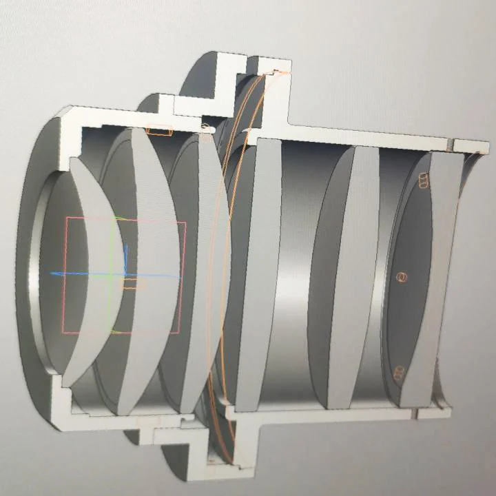
Three windows lay between the object and the lens. Two fused-silica windows were 2 mm thick, and a Kodial 7056 borosilicate-glass window was 8 mm thick. Their materials, thicknesses and positions were included in the model because each plate introduces aberrations into a diverging beam.
Our team designed the lens system, assessed the detected energy and revised the lens after clarifying refractive indices and tolerances. Updated drawings were released for manufacturing, followed by revised lenses and mechanical parts.
The technical brief required anti-reflection coatings at the operating wavelength. The target transmission was at least 85% at 396 nm.
 MODEL 01
Optomechanics
Mechanics connecting two planes of the setup
The object plane was horizontal, while the image plane was vertical. Our team added a folding mirror in an adjustable mount. The design provided manual position and angular adjustment, a replaceable interference filter in front of the sensor and a light shield.
A motorised support on linear guides was developed to move the lens. Its mechanics had to reposition the optical system under computer control while maintaining focus. The project included a 3D model, manufacturing drawings, a lens mount, a support and parts, some of which were manufactured by abrasive waterjet cutting.
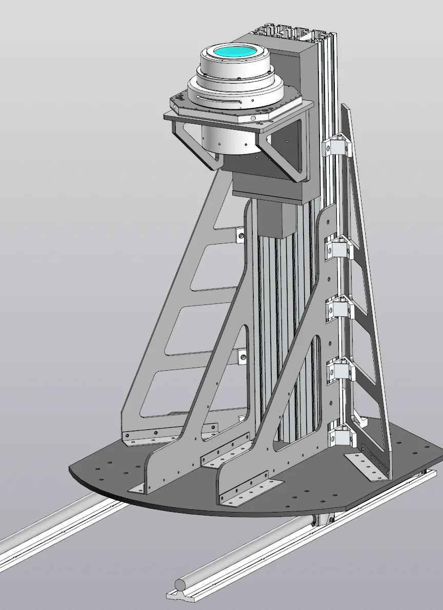 PHOTO 02
Cleanroom assembly
Optical unit assembled in a cleanroom
The optical unit was assembled in an ISO 6 cleanroom. The photographs show work with a large-aperture optical element and the assembled lens housing before integration with the mechanical system.
The mechanical and optical designs were refined in parallel. After clarifying tolerances, our team updated the lenses, manufactured new parts and reassembled the units. The finished lens was integrated with the mechanics, packed in a protective case and shipped to the client.
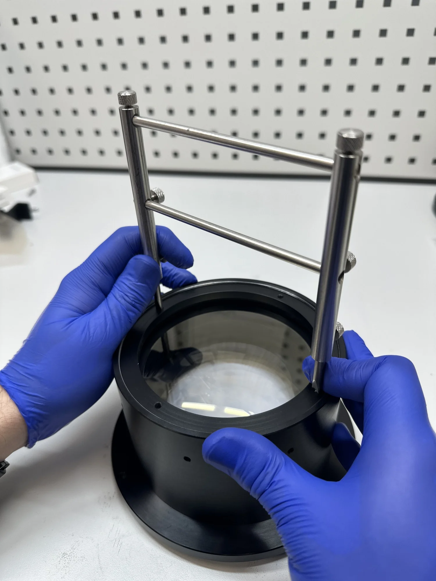 PHOTO 03
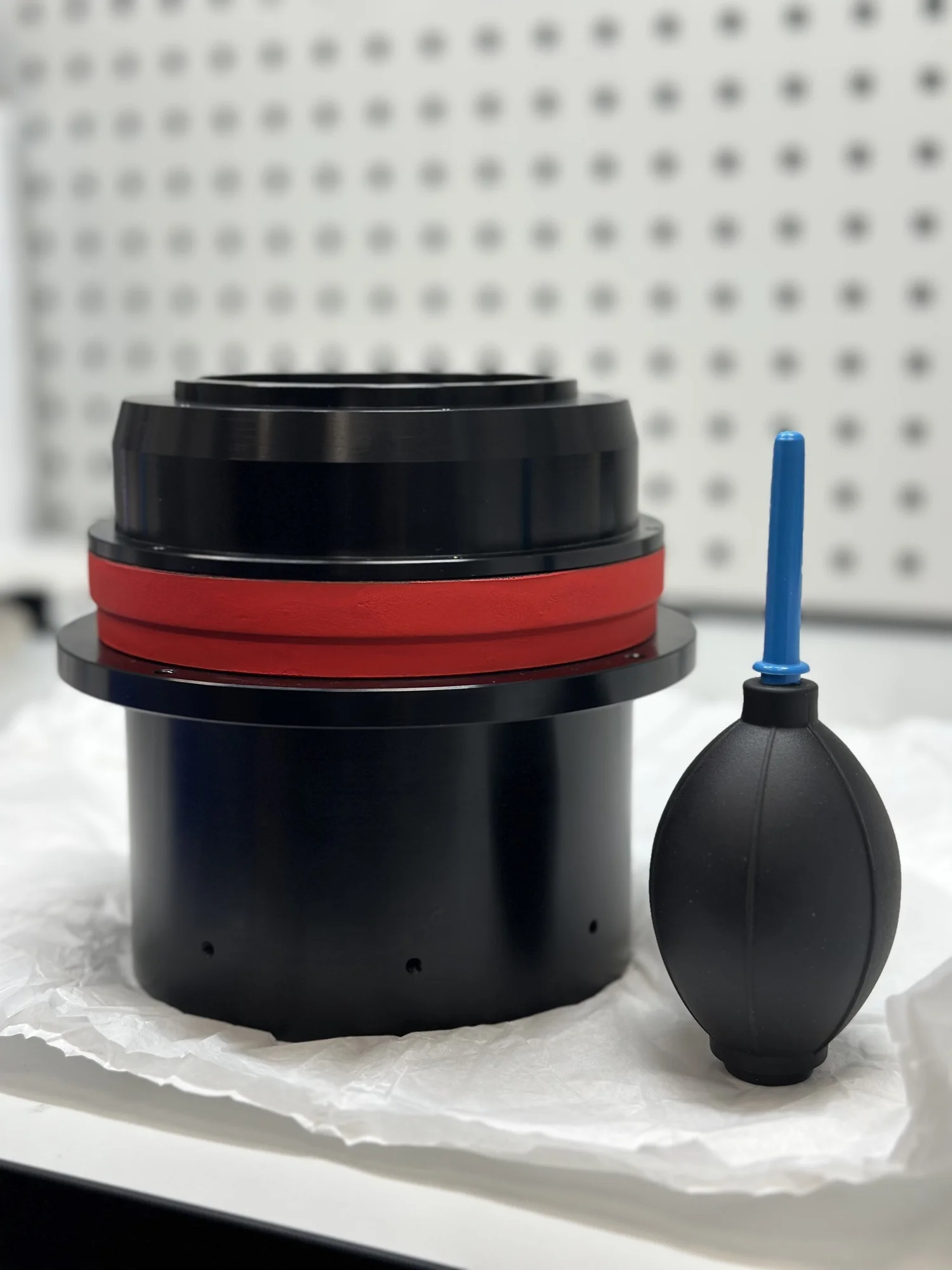 PHOTO 04
Result
Lens and mechanical system delivered to the client
Our team delivered the lens and mechanical system for integration into the experimental setup. The project covered optical design, lens revisions after material clarification, motorised mechanics, component manufacturing and cleanroom assembly.
Within a single engineering process, the project progressed through prototyping and manufacturing and assembly.
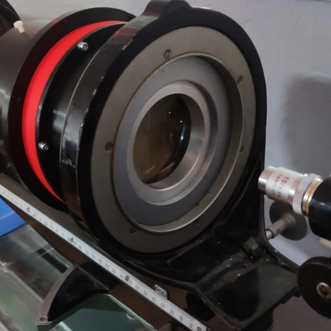 PHOTO 05
Discuss a similar project
Send a technical brief, object and detector parameters or a description of the experimental setup. Our team will review the task and propose the scope of design, prototyping and manufacturing.