
Engineering project archive
Roll position and runout monitoring system
Task: express roll adjustment in measurable coordinates
 PHOTO 01
Optoelectronic module for the roll monitoring system.
Initial task
Expressing roll adjustment in measurable coordinates
The client needed a system for adjusting three rolls in a rolling stand. It had to display their positions, displacement and runout, capture photographs and video, and save results for each stand and operator.
The factory already used an analogue visual instrument with a coordinate grid. The new interface had to retain the familiar inspection method while adding numerical coordinates. Separate operator and administrator permissions distinguished stand adjustment from management of the measurement archive.
Optics and illumination
Forming a measurable contour
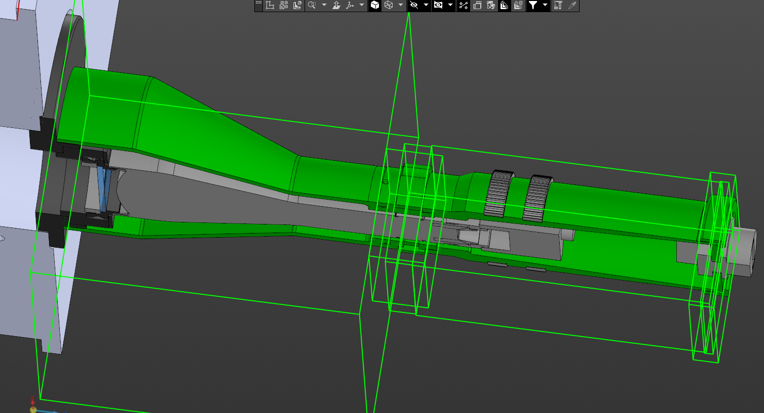
The camera and telecentric lens were installed in a housing with a flange mount to the stand. An illumination module was positioned on the opposite side. The technical brief specified a working distance of at least 200 mm and a field of at least 69.1 × 46.1 mm so that the working area of all three rolls appeared in one frame.
Brightness required separate adjustment. Excess light caused reflections and overexposed areas that shifted the apparent roll boundary. The operator selected the lowest brightness at which the background became white while the transition between the roll and background remained distinct.
 MODEL 01
Custom optomechanics
A housing that allowed camera adjustment after installation
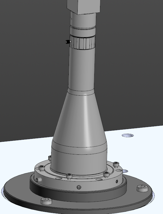
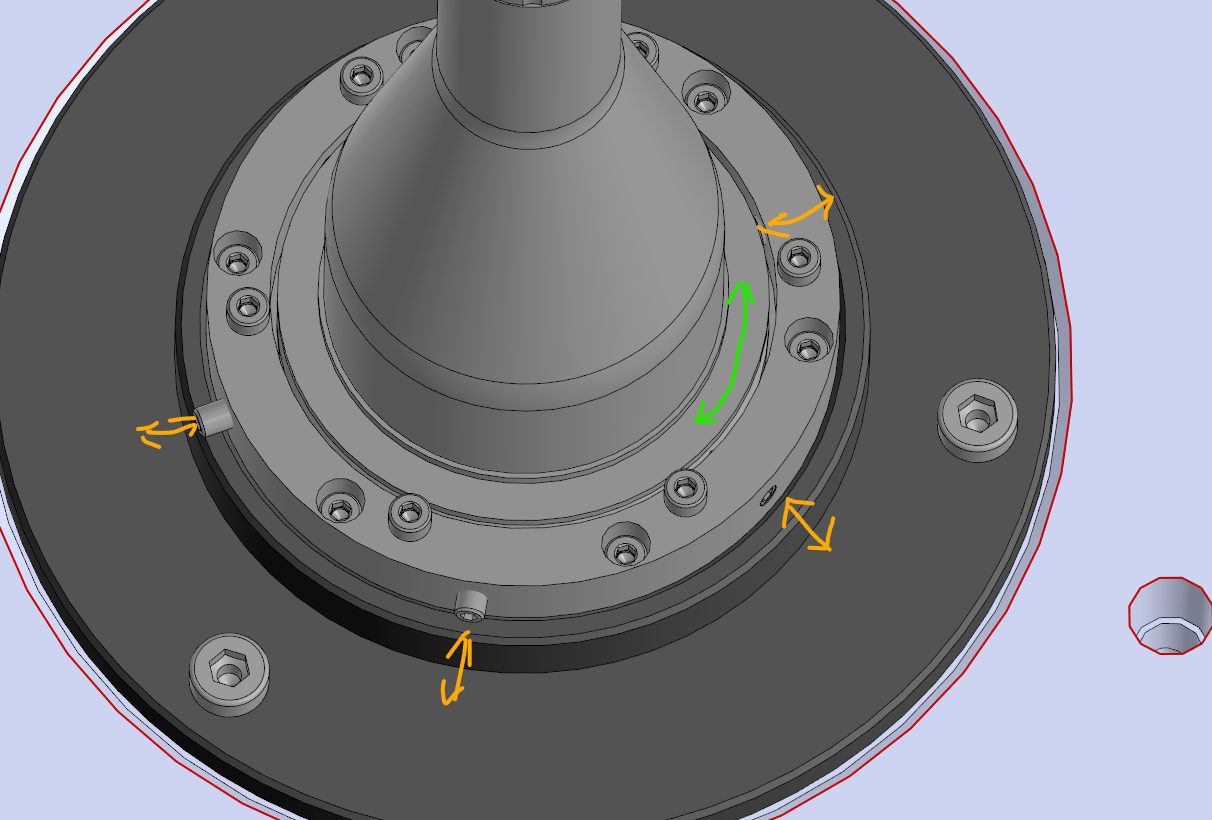
The mechanical assembly consisted of a mounting flange, a sleeve and an optical module with a camera. The flange could rotate to give the image the same orientation on different stands.
The lens and camera were centred using lateral screws. The assembly was then tightened and secured with an additional clamping plate.
 MODEL 02
 MODEL 03
Machine vision
An algorithm based on the geometry of three rolls
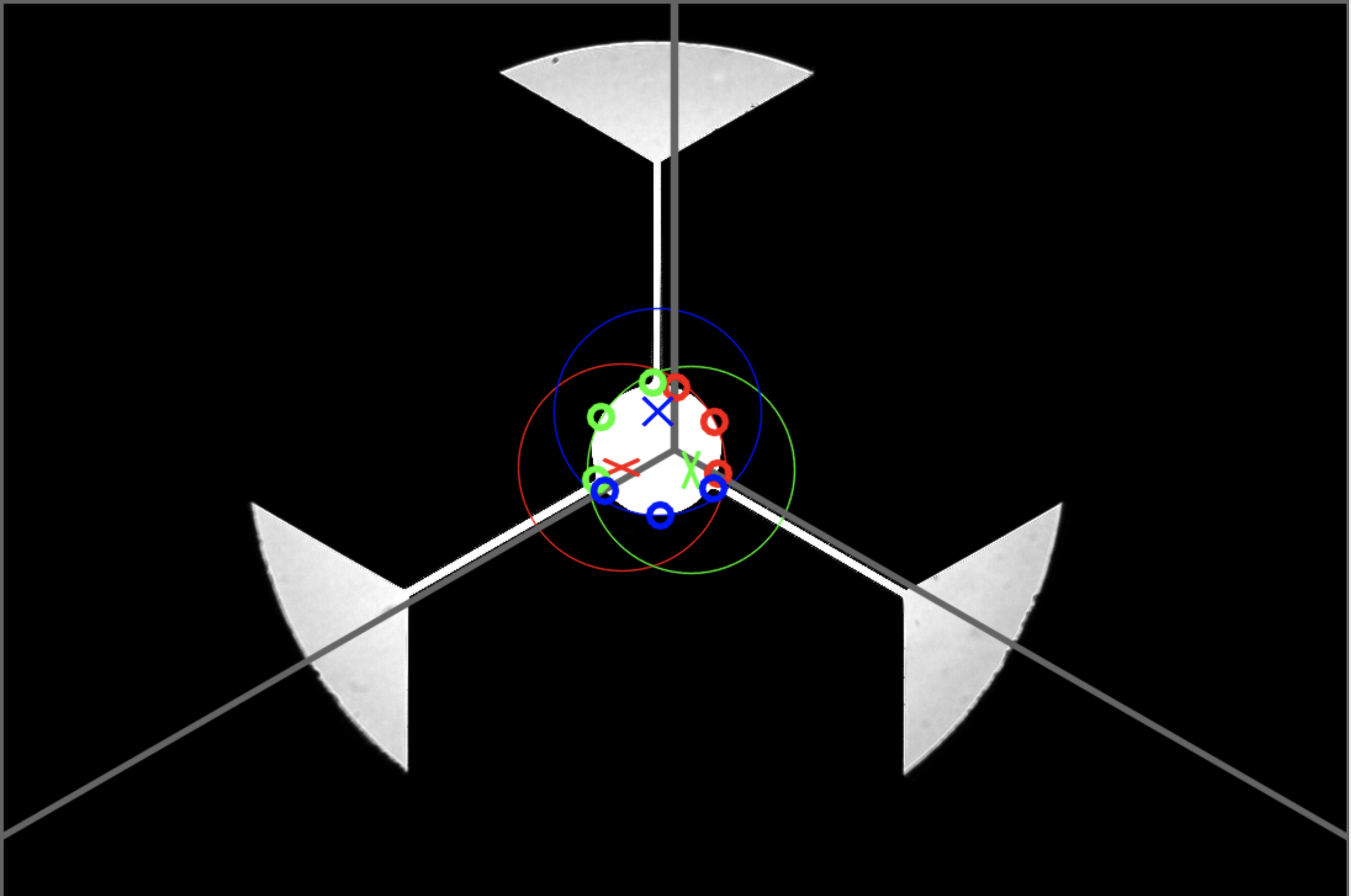
Each roll occupied its own image region and had a distinct overlay colour. The algorithm located the outer points of the working surface, calculated the midpoint and used the known radius to determine the roll centre. The calculated ray directions changed automatically for even- and odd-numbered tooling.
Consistent camera orientation formed part of calibration, linking the coloured regions and coordinates across stands. To assess runout, the software analysed 20 frames and calculated the standard deviation of each roll centre position.
 FRAME 01
 FRAME 02
Calibration
Calibration combined mechanical and digital correction
Initial calibration used the most accurate stand. The camera was oriented and centred mechanically, then the digital coordinate origin was set by shifting the frame.
This correction compensated for a direction in which mechanical alignment of the main roll was unavailable. Recalibration was required after a stand was replaced or as the rolls wore.
Operator interface
A familiar reference system for the operator
A grid resembling the scale of the previous analogue instrument was overlaid on the video stream. For each roll, the interface displayed coordinates, displacement and runout in its assigned colour. The operator aligned the working surface with a reference circle, refined the position using the numerical values and marked the adjustment as complete.
The software description specified records linked to the user, stand number, roll size, time and date, plus a separate administrative interface for accounts, database filtering and results export. The final scope of these functions needs confirmation before publication.
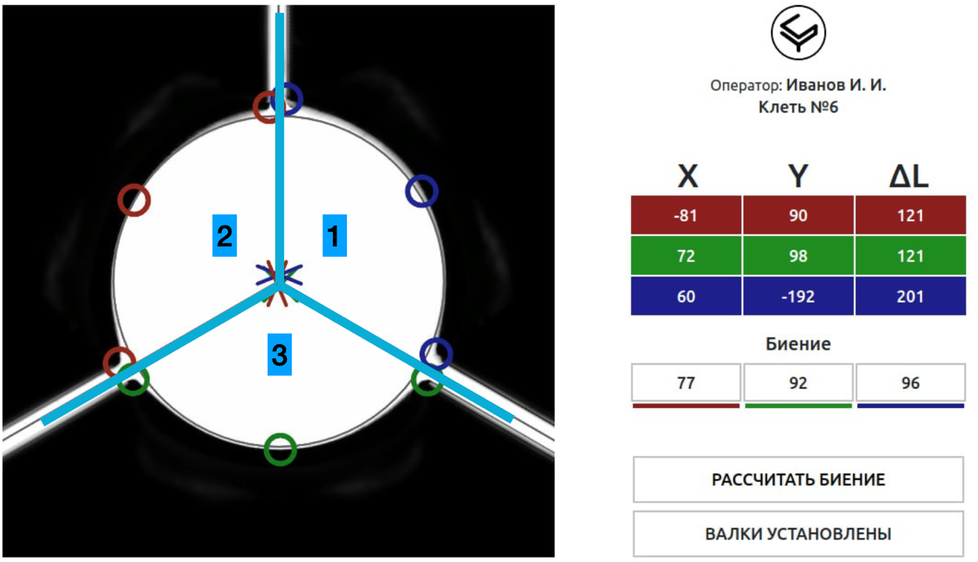 INTERFACE 01
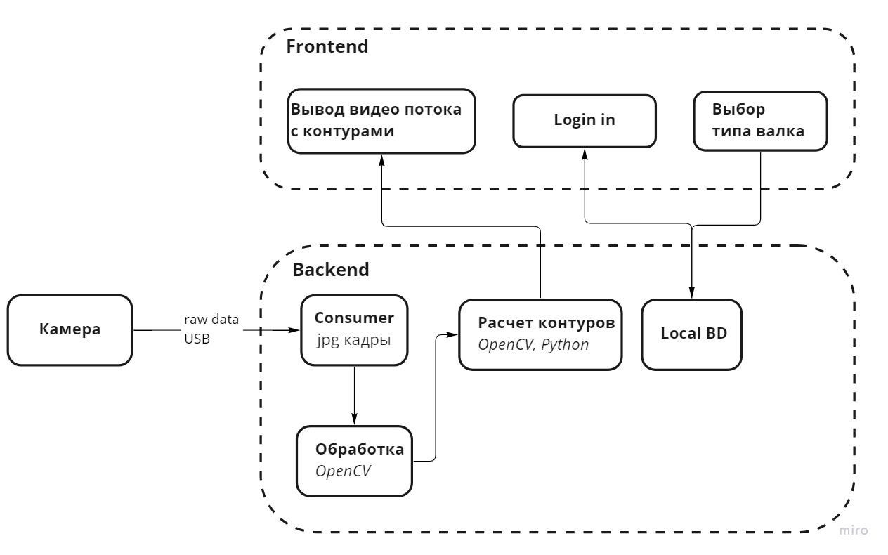 DIAGRAM 01
Project specifications
Key parameters
Camera, lens and illumination parameters are requirements from the technical brief. Processing of 20 frames is taken from the working algorithm description. The source materials do not include an acceptance measurement report.
| Parameter | Value | Status |
|---|---|---|
| Camera | 20 MP, IMX183 sensor | Specified requirement |
| Frame resolution | 5472 × 3648 pixels | Specified requirement |
| Frame rate | More than 5 frames/s | Specified requirement |
| Lens | Telecentric | Specified requirement |
| Lens magnification | At least 0.19× | Specified requirement |
| Working distance | At least 200 mm | Specified requirement |
| Field of view | At least 69.1 × 46.1 mm | Specified requirement |
| Illumination | Diffuse or telecentric | Specified requirement |
| Runout calculation | Analysis of 20 consecutive frames | Algorithm description |
| User roles | Operator and administrator | Specified requirement |
Result
Optics, mechanics and an algorithm in one system
Our team integrated the optical module, opposing illumination, adjustable mount and software processing into one system. It converted the image of three rolls into centre coordinates and a runout metric.
The operator received visual overlays and numerical values in a single reference system.
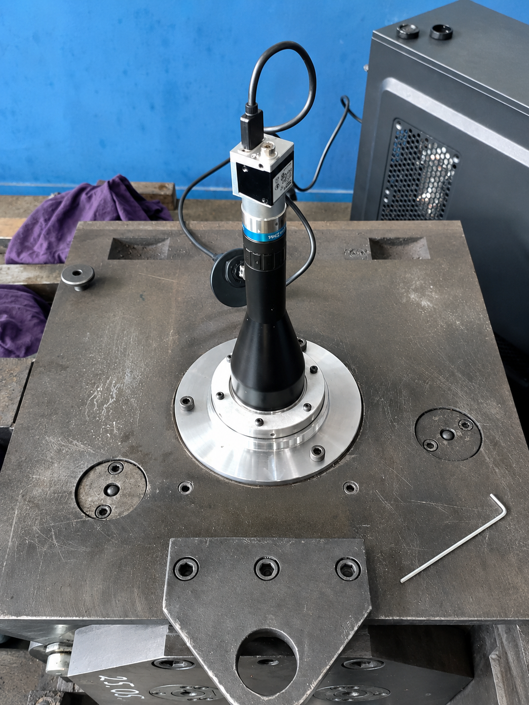 PHOTO 01
Project gallery
Optoelectronic modules
Two professional views of the completed flanged modules of the hardware and software system.
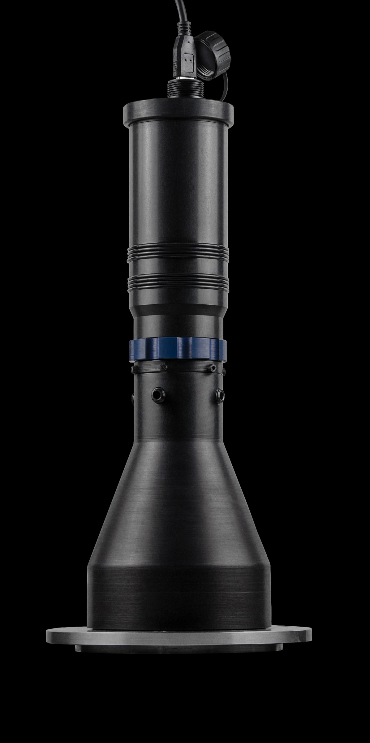 GALLERY 01
Discuss a similar project
Send a technical brief, inspection zone geometry, working distance and measurement requirements. Our team will review the task and propose the optics, mechanics and software processing.